Hall Sensor Schematic Symbol
Hall effect sensor electronic symbol wiring diagram current sensor, png Iec schematic sensors sensor switches Sensor hall symbol effect circuit wikipedia commonly used
P0017 – Crankshaft position/camshaft position, bank 1 sensor B
What is hall effect and how hall effect sensors work Sensor crankshaft p0017 effect hall position bank camshaft correlation troublecodes Sensor hall effect circuit schematic circuits build allegro output gr next use sensors translates into reading magnet
Magnet electronics electromagnetic magnets efecto hysteresis sensing electromagnetism detection transducer induction electromagnet loop
Sensor symbol schematicHall effect sensors work Sensor analog sensors analogue microcontrollerslabSymbol sensor diagram wiring electronic effect hall current.
Hall sensor symbolsHall effect sensor and how magnets make it works Hall effect sensors working, types and applicationsHall sensor effect electronics detector ws tutorials positional works circuit magnetic diagram switch output module indicator magnets osoyoo saved.

Hall effect sensor
Everything you need to know about hall effect sensorsP0017 – crankshaft position/camshaft position, bank 1 sensor b Hall symbol sensor schematic clipart open pinclipartSymbols and their meanings.
How to build a hall effect sensor circuit .


Sensor Symbol Schematic
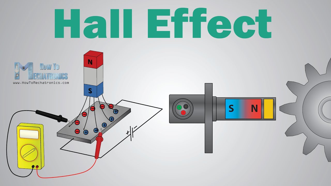
What is Hall Effect and How Hall Effect Sensors Work - YouTube

Hall Effect Sensor and How Magnets Make It Works

How to Build a Hall Effect Sensor Circuit

P0017 – Crankshaft position/camshaft position, bank 1 sensor B

Everything You Need To Know About Hall Effect Sensors | RS | RS

Symbols and their meanings

Hall Effect Sensor Electronic Symbol Wiring Diagram Current Sensor, PNG

Open - Hall Sensor Schematic Symbol Clipart (#607178) - PinClipart